SHERER ARCHITECTS

Categories
Uncategorized

How to Read Architectural Drawings Without Getting Overwhelmed

When you first open a set of architectural drawings, it can feel like trying to decipher an ancient text. The sheer number of sheets, lines, and symbols can be overwhelming, especially for clients and stakeholders who don't live in this world every day.

The secret isn't to memorize every symbol overnight, but to learn how to navigate the set. Think of it like a map. Once you understand the legend and how to find your starting point, the whole journey becomes clearer.

Your First Look at a Set of Architectural Drawings

Every professional drawing set is organized with a clear logic, moving from the big picture down to the smallest details. It's a system designed to guide you through the project's story, piece by piece. Knowing where to begin is half the battle.

Start with the Title Block

Before you even try to understand a floor plan or an elevation, find the title block. This is the rectangular box of text, almost always located in the bottom-right corner of the sheet. It's the drawing's Rosetta Stone.

Seriously, don't skip it. The title block is packed with crucial context:

  • Project Name and Location: First things first, make sure you're even looking at the right project.
  • Sheet Title and Number: This tells you exactly what you're seeing ("First Floor Plan," "Building Section A") and where it fits in the full set (e.g., A-101).
  • Architect's Information: Shows who is responsible for the design.
  • Drawing Scale: This is absolutely critical. It defines the ratio of the drawing to the real world (e.g., 1/4" = 1'-0").
  • Revision History: A log of changes. Always check this to make sure you're working from the latest version and not an outdated plan.

Always check the title block first. I've seen meetings go completely off the rails because someone was looking at an old revision. It's the single most important habit to build.

The Core Drawing Types

With your bearings set, you can start to make sense of the main drawings that tell the project's story. A complete set might contain dozens of specialized drawings, but nearly everything boils down to three fundamental views: plans, elevations, and sections.

Before we dive into each one, here's a quick reference guide to the essential elements you'll find on nearly every architectural drawing sheet. Think of this as your cheat sheet for getting oriented quickly.

Key Components of an Architectural Drawing Sheet

Component What It Tells You Why It's Important
Title Block The drawing's ID: project name, sheet title, number, scale, and revision date. Provides immediate context so you know exactly what you're looking at.
North Arrow The orientation of the building or site relative to true north. Essential for understanding sunlight, site context, and how the building is positioned.
Scale Bar A graphical representation of the drawing's scale (e.g., a marked line showing 10 feet). Allows for quick visual measurement without needing a special ruler.
Key Plan A small diagram showing which part of the overall building this specific sheet focuses on. Helps you locate where a detailed drawing fits into the larger project.
Legend/Key A list of symbols, line types, and abbreviations used on the sheet and what they mean. The "dictionary" for the drawing, translating symbols into real-world items like doors or outlets.

This table covers the "metadata" of a drawing. Getting comfortable with these components will make reading the actual plans, elevations, and sections much more intuitive.

A plan is a bird's-eye view, looking straight down as if the roof were removed. This is where you'll see the layout of rooms, the thickness of walls, and the locations of doors and windows. It's all about horizontal relationships and flow.

An elevation is what the building looks like from the outside, viewed head-on. You'll have a separate elevation for each side (North, South, East, West). This is where the building's aesthetic comes to life—you'll see exterior materials, window styles, and roof pitches.

A section is like slicing a cake. It's a cut through the building that reveals its internal construction. Sections are invaluable for understanding vertical relationships, like ceiling heights, floor thicknesses, and how different levels connect.

These three views work together. A floor plan shows where a window is, the elevation shows what it looks like, and a section shows how tall it is from the floor. Understanding this interplay is the foundation to read construction blueprints like a pro. Once you've got this down, you're ready to tackle the finer details.

Getting to Know the Main Architectural Plans

Architectural drawings tell the story of your project from several different angles. The real trick to understanding them is learning how these views connect. Don't think of them as separate documents; they're more like interconnected layers that, when pieced together, give you a complete, three-dimensional picture of the final build.

We'll start with the widest view and zoom in from there, looking at the three most common types of plans you'll see in any set of drawings. Each one answers a different, crucial question about your future space. This whole system is organized to move from the macro to the micro, as you can see below.

A concept map illustrating the organization of architectural drawings, showing site plans, elevations, and floor plans.

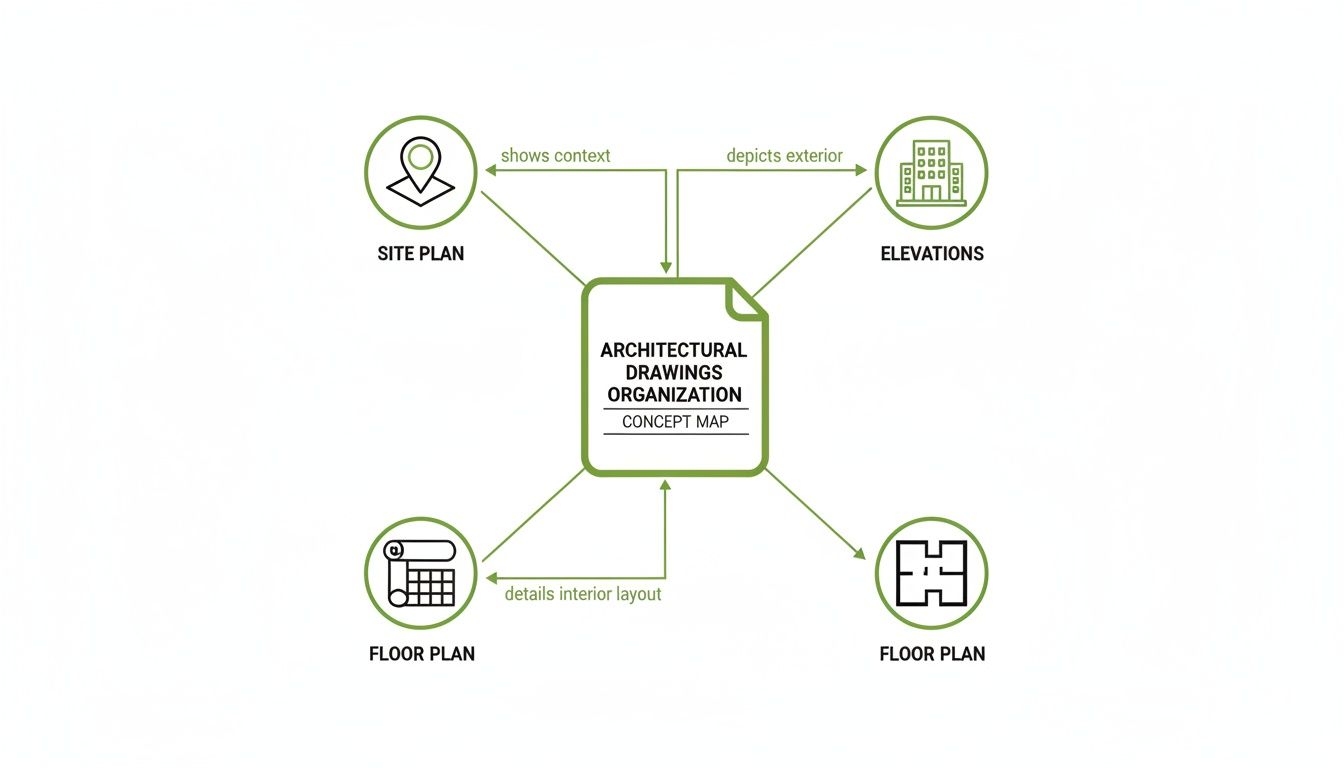
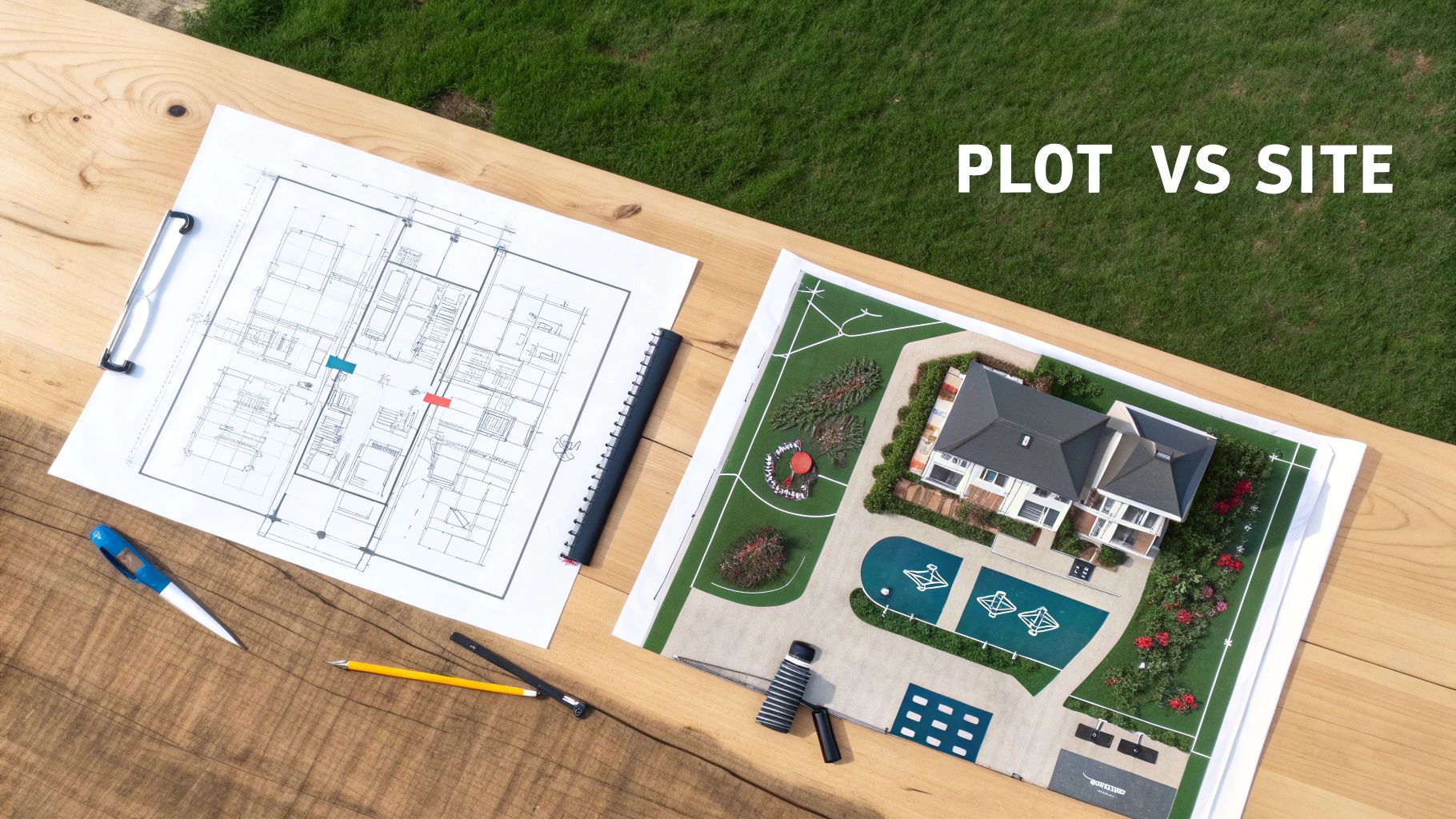
This map shows how everything ties together—the site plan gives context, the floor plan details the layout, and the elevations show what it all looks like from the outside.

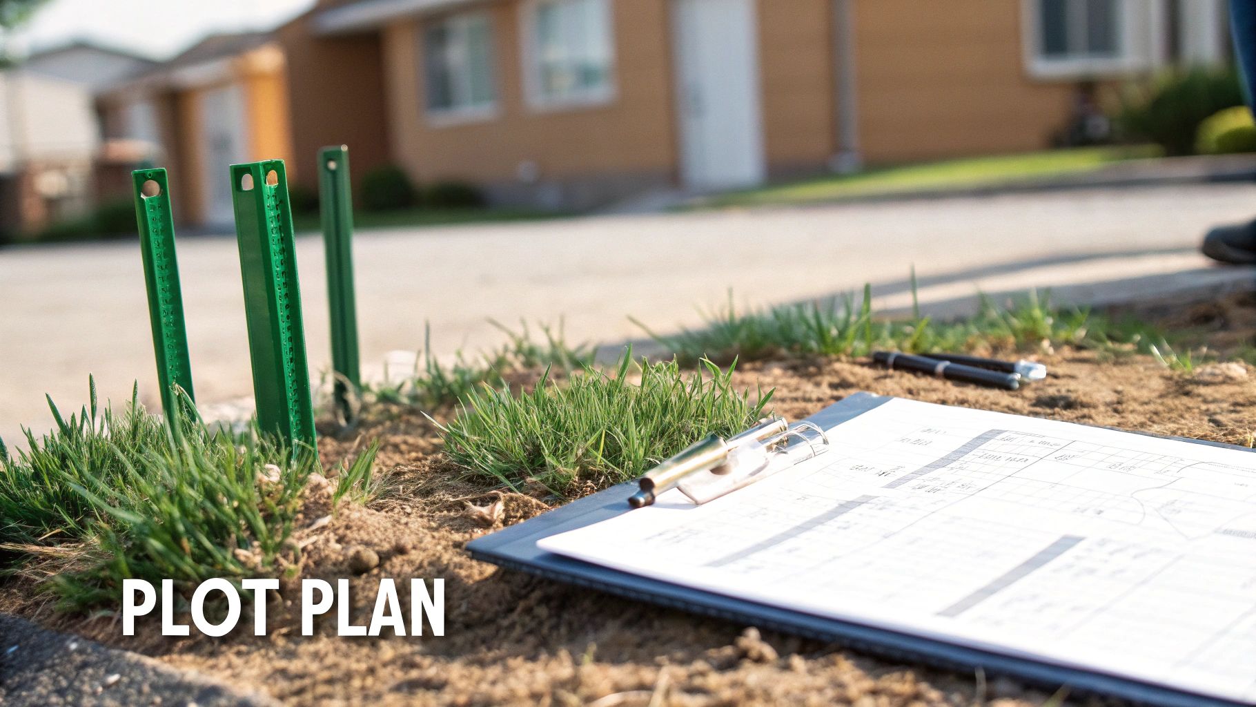
The Site Plan: The 30,000-Foot View

First up is the site plan. This is your project's command center, a top-down view of the entire property that shows how the building fits into its surroundings. It’s where you see the forest before you start looking at the individual trees.

But a site plan is about much more than just the building's footprint; it’s all about context. Here’s what you’ll find:

  • Property Lines: The legal boundaries of your land.
  • Building Placement: Exactly where the structure sits, including setbacks from property lines.
  • Topography: Contour lines that map out the slope and elevation changes across the site.
  • Landscaping: Locations for trees, walkways, driveways, and any planned green space.
  • Utilities: Where connections for water, sewer, gas, and electricity will be.

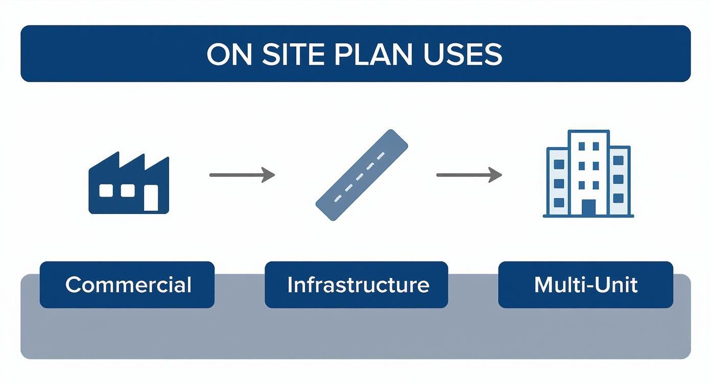
Let's say you're developing a new retail space. The site plan is what will show you exactly where customer parking is, how shoppers will walk from the street to your front door, and how delivery trucks will get to the back. It’s the master plan for the whole property.

The Floor Plan: Stepping Inside

Once you've got the lay of the land, the floor plan takes you inside. This is the drawing most people recognize—it’s that classic bird's-eye view, as if someone sliced the roof off to show the layout of a single level. As you get comfortable with the different plan types, it’s a good idea to begin to understand how to read floor plans specifically, since they are the heart of any design.

The floor plan is all about the relationship between spaces. You can see the flow from a lobby to conference rooms, get the exact dimensions of an office, and pinpoint the locations of every wall, door, and window. This drawing answers the most important question: "How will this space actually work?"

A floor plan isn't just a layout; it's a script for how people will move and interact inside the building. Try to trace your own path from the entrance to your office. Does it feel natural? Can you spot potential bottlenecks? Figuring this out now will save you from major headaches down the road.

This is also where the details start to come into focus. Look for symbols that show plumbing fixtures in the restrooms, casework for reception desks, and which way the doors swing—a small detail that’s critical for accessibility and figuring out where furniture can go.

The Reflected Ceiling Plan: A Look Up

Finally, let's look up. The Reflected Ceiling Plan (RCP) can be a little strange at first glance. It’s another top-down view, but this time, you’re looking at a mirror image of the ceiling as if it were projected onto the floor below.

Why a mirror image? Because the RCP is the master coordinator for everything happening overhead. It’s the roadmap for your electricians, HVAC technicians, and lighting designers. On an RCP, you'll find:

  • Lighting Fixtures: The precise location and type of every single light.
  • HVAC Vents: Where the supply and return air diffusers are located.
  • Fire Safety Systems: The placement of sprinkler heads and smoke detectors.
  • Ceiling Finishes: Details on materials, like acoustic ceiling tiles or an exposed concrete finish.

For instance, while a floor plan might show a large conference room, the corresponding RCP will detail the exact grid of recessed lights, where the projector will be mounted, and how the air conditioning vents are positioned for everyone’s comfort. It’s an essential, though often overlooked, part of the puzzle.

While plans give you that crucial bird's-eye view, they don't tell the whole story. To truly understand a building's three-dimensional form, its appearance, and how it’s all put together, you need to look at a different set of drawings. Elevations, sections, and details are what bring the flat layout to life. Learning to connect these different views is the key to seeing the project as a single, coherent vision.

Architectural drawings and rolled blueprints on a wooden desk, with a pen and 'Elevations and Sections' sign.

This method of cross-referencing different views has deep roots. It was largely standardized during the Renaissance, with Andrea Palladio’s 1570 masterpiece, I Quattro Libri dell'Architettura, setting the stage. His work used precise orthographic projections—the front, side, and top views we still rely on today. This system brought incredible clarity to construction, and its core principles live on. Modern Building Information Modeling (BIM) workflows, which are built on this idea of integrated views, have been shown to slash project misinterpretations by up to 30%. To see how these foundational ideas developed, you can explore the rich history of architectural drawings.

To help clarify the role of each drawing, let's look at what each one is designed to communicate.

Table: Drawing Types and Their Purpose

Drawing Type Perspective Key Information Provided
Elevation Looking at the building from the outside, straight on. Shows exterior finishes, window/door styles, roof shape, and overall aesthetic.
Section An imaginary vertical slice through the building. Reveals interior ceiling heights, floor/roof construction, and how spaces connect vertically.
Detail A magnified, close-up view of a specific connection. Shows how different materials and components are assembled at a critical junction.

This table provides a quick reference, but let's dive into what you'll actually see on each of these sheets and why it matters for your project.

Elevations: The Face of Your Building

Think of an elevation as a flat, head-on photograph of one of your building's exterior faces. A complete set usually gives you four primary views, one for each side of the building, labeled according to the direction they face: North, South, East, and West.

These drawings are all about the building's curb appeal and external features. This is where your architect communicates the final look and feel.

On an elevation, you'll find things like:

  • Exterior Materials: Finishes like brick, metal paneling, or stucco are shown and labeled.
  • Window and Door Styles: You'll see the exact design, size, and placement of all exterior doors and windows.
  • Rooflines: The elevation clearly shows the pitch, shape, and material of the roof.
  • Vertical Heights: Key dimensions are noted here, like the height from the ground to the eaves or from one floor to the next.

For example, if you're reviewing plans for a new storefront, the front elevation is where you'll see the scale of the display windows, the design of the main entrance, and exactly where your signage will be placed. It’s your first look at the finished product.

Sections: Slicing the Building in Half

If an elevation is the outside view, a section drawing gives you a look inside by making an imaginary vertical cut right through the building. Picture slicing a layer cake and looking at it from the side—that's a section. It reveals the building's internal anatomy and how all the different parts stack up.

Section drawings are absolutely critical for understanding the building's structure and the feeling of its interior volumes. On your floor plan, you’ll see a "section cut line"—a long line with an arrow at each end—showing precisely where this imaginary slice was made and which direction you're looking.

A section reveals crucial information you can't get from other drawings:

  • Ceiling Heights: This is the only place to truly see and confirm the height of each room.
  • Floor and Roof Construction: You can see the thickness of floor slabs and the layered assembly of the roof structure.
  • Vertical Relationships: Sections clearly show how stairs connect different levels, how atriums or light wells are constructed, and what double-height spaces actually feel like.

A section cut is the ultimate reality check for a building’s interior. It’s where you can really visualize the experience of being in the space—confirming a ceiling feels tall enough or that a staircase is as grand as you pictured.

Details: The Magnifying Glass

Finally, detail drawings zoom in on specific, complex areas where multiple materials or components come together. While a section might show an entire wall, a detail drawing will show exactly how the window is sealed into that wall, complete with every layer of flashing, insulation, and sealant.

These drawings are done at a much larger scale (like 1 1/2" = 1'-0" or even bigger) to show these intricate connections with perfect clarity. They are absolutely essential for the builder to ensure quality construction and prevent future problems like water leaks or air infiltration.

You’ll typically find detail drawings for tricky areas such as:

  • Window head, jamb, and sill conditions
  • Roof-to-wall intersections
  • Foundation and footing connections
  • Custom-built features like reception desks or stair railings

By learning to move between these three types of drawings, you get the complete picture. The elevation shows you the beautiful custom window, the section shows you its height within the wall, and the detail drawing shows the builder exactly how to install it to perfection.

4. Getting to Grips with Scales, Symbols, and Schedules

A wooden ruler, pen, and document on a drafting table, with a sign showing 'Scales and Symbols'.

If the plans and elevations are the main story of a project, then the scales, symbols, and schedules are the fine print where all the critical details live. This is where you move from the big picture to the nuts and bolts—confirming the real-world size of a conference room, identifying every single electrical outlet, and finding the exact model number for the lobby doors.

Getting this part right is absolutely essential. Misinterpreting these elements is one of the quickest ways for a project to go off the rails, leading to costly mistakes and delays.

Cracking the Code of Architectural Scales

An architectural scale is simply the ratio that translates the lines on paper to their actual size once built. Without it, a drawing is just a bunch of abstract lines. You'll almost always find the scale for each drawing sheet listed in the title block, usually in the bottom-right corner.

For commercial projects, you'll run into a few common scales over and over:

  • 1/8" = 1'-0": This is often used for large-scale floor plans. The main goal here is to show the overall layout and flow of a building without getting bogged down in minute details.
  • 1/4" = 1'-0": A real workhorse scale. It’s perfect for most floor plans and building elevations because it offers a great balance between seeing the whole picture and still having enough clarity for key components.
  • 1 1/2" = 1'-0": When you need to see exactly how something complex comes together, you'll see a detail drawing at this larger scale. It's how architects clearly show intricate connections, like how a window frame is flashed and sealed into a brick wall.

The jump from hand-drafting to Computer-Aided Design (CAD) has made understanding scale even more critical. The 1982 launch of AutoCAD was a game-changer, boosting precision by an incredible 90% in major markets. But with digital files that can be zoomed in and out, it's easy to lose perspective. In fact, misreading digital plans now contributes to 37% of construction rework, costing an eye-watering $150 billion worldwide each year. You can learn more about the evolution of drafting and how it shapes the drawings we use today.

The Universal Shorthand of Symbols

Think of symbols as a visual shorthand that keeps drawings from becoming a cluttered mess. Instead of writing "duplex electrical outlet" or "double-hung window" dozens of times, architects use standardized symbols.

A drawing without a legend is like a map without a key. The first thing you should do when you get a new set of plans is find the legend. It's your dictionary for the entire project.

The symbol legend is usually on one of the first few sheets. It decodes every symbol used in the drawing set. While there are thousands of symbols out there, you'll see a few categories on virtually every project.

Common Architectural Symbols to Know

Symbol Category What It Represents Real-World Example
Doors Shows the location, size, and swing direction. A simple arc indicates which way the door opens. A line with an arc swinging into an office, indicating a 3-foot wide door.
Windows The placement, type, and size. Different line patterns can show if a window is fixed, casement, or sliding. A basic rectangle inside a wall line, representing a fixed picture window.
Electrical The locations for all outlets, switches, light fixtures, and data ports. A small circle with two parallel lines through it, marking a standard wall outlet.
Plumbing The placement of sinks, toilets, floor drains, and other fixtures. An oval shape drawn into a countertop, representing a sink basin.

Once you learn to spot these, you can scan a floor plan and immediately understand how a space works—where people will turn on the lights, plug in their laptops, and find the restrooms.

Bringing Order with Schedules

Finally, we have schedules. In the world of architecture, a schedule isn't a timeline; it's a super-organized table that provides exhaustive detail about specific building components. It's basically a spreadsheet embedded right into the drawings.

Schedules are a brilliant way to manage repetitive items. Imagine trying to label every single door on a floor plan with its size, material, fire rating, and hardware. The drawing would be unreadable. Instead, each door gets a unique tag (like 101, 102A, etc.) on the plan.

You then flip to the Door Schedule to find every last detail for door 101. Some of the most common schedules you'll rely on are:

  • Door Schedule: The master list of every door's type, size, material, fire rating, and hardware set.
  • Window Schedule: Details the model, size, glazing type, and finish for every window.
  • Finish Schedule: A room-by-room breakdown of finishes—wall paint color, flooring material, baseboard type, and ceiling style.
  • Lighting Schedule: Specifies the manufacturer, model number, and lamping for every single light fixture.

When you need the definitive answer on a specific item, the schedule is your source of truth.

How to Review Drawings with Your Architect

Walking into a design review meeting can be intimidating, with a full set of architectural drawings spread out on the table. But having a successful meeting isn't about knowing every last symbol. It's about having a game plan. With a structured approach, you can give feedback that truly matters and make sure the final building works for you.

When you sit down with your architect, the natural impulse is to dive right into the little things. Resist it. The best way to tackle a set of drawings is to start big and work your way down to the details. I always tell my clients to think of it as a three-pass system: first, the big picture flow; second, the individual rooms; and third, all the nitty-gritty details. This keeps you from getting lost in the weeds and helps you spot major issues before they become expensive problems.

Start with the Overall Flow and Layout

Your first pass is all about the journey. Lay out the floor plan and literally trace with your finger the paths people will take. Imagine you're a customer walking in for the first time, an employee rushing to a meeting, or a delivery person trying to find the service entrance.

As you follow these paths, ask yourself some basic questions about the experience:

  • Is the path obvious? Or would someone need a map to find the main conference room? Good design feels intuitive.
  • Where are the traffic jams? Look for narrow hallways or intersections that are going to feel crowded during busy hours.
  • How do key spaces relate to each other? Does the flow between the reception area, meeting rooms, and restrooms make sense?

Think of this first pass as reading the building's "story." You're evaluating how the physical layout will shape behavior. Don't worry about furniture or finishes just yet—focus on the permanent walls, doors, and hallways that define the core experience.

Zoom in on Room Dimensions and Function

Okay, once you're comfortable with the overall circulation, it's time for pass number two. Now you can zoom in on specific rooms and spaces. This is where you start connecting the lines on paper to how the space will actually be used every day.

Look at the dimensions and try to get a real feel for the scale. An empty box on a drawing is one thing, but reality is another. Is a 10' x 12' office really big enough for a desk, a filing cabinet, and a couple of guest chairs? Will people be able to comfortably pull out their chairs in the conference room without bumping into the wall? If you can't visualize it, ask your architect to point to a room in your current building that's a similar size.

A classic mistake is getting sidetracked by aesthetics too early. Before you even think about paint colors, ask your architect: "Walk me through a typical day in this room." This simple question forces a conversation about function, which is where you can provide the most valuable feedback.

Check the Details: Window Placement and Door Swings

Finally, it’s time for your third and most detailed pass. This is where you hunt for the small things that can have a surprisingly huge impact on how a space feels and functions. We're talking about window placement, door swings, electrical outlet locations, and storage.

Go through the plan room by room and ask pointed, practical questions.

  • "How does the light change in here throughout the day?" This will tell you if the window placement is going to create glare on computer screens at 3 PM or leave a corner perpetually dark.
  • "Show me exactly where we'll store X, Y, and Z." Don't just assume closets will appear. Make sure there’s dedicated, adequate storage for everything from office supplies to cleaning equipment.
  • "Which way does this door swing?" A door that swings into a tight space can render half the room useless or create an awkward collision with furniture. Check every single one.

A good design review is a conversation, not a presentation. By using this method, you become a true collaborator in the process. Remember, changes on paper are cheap. Changes made once construction has started are anything but.

Common Questions We Hear All the Time

Even when you've got the basics down, a few practical questions almost always pop up during review meetings. These are the "what-if" and "how-do-I-know" queries that come from digging into the details. Getting these answers straight will give you a real boost of confidence when you're flipping through a set of plans.

Think of this as the final piece of the puzzle. You know what the different drawings are; now let's talk about how they actually work together on a fast-moving project.

"What Do All These Dashed Lines Mean?"

This is probably the number one question we get. You'll see solid lines, dashed lines, and sometimes even dotted lines, and they all mean something different. While solid lines represent things you can see—like walls, doors, and windows—dashed lines almost always point to something that's not immediately visible from that particular viewpoint.

You'll run into them in a few common situations:

  • Things Above You: On a floor plan, dashed lines often show elements that are above the typical four-foot "cut" line. Think of kitchen wall cabinets, a ceiling beam, or the line of a roof overhang outside.
  • Things Below You: They can also show what's hidden underneath a surface. A classic example is seeing the dashed outline of a building's foundation on a site plan.
  • Things That Are Changing: In renovation work, dashed lines are your go-to for figuring out what's coming down. They’re frequently used to show walls, doors, or fixtures marked for demolition.

When in doubt, always hunt for the legend on the drawing sheets. It's the official decoder ring for what every line type, symbol, and abbreviation means for that specific project.

"How Do I Know I'm Looking at the Latest Version?"

This is a huge one. Working from an old set of drawings is a classic—and costly—mistake. The single source of truth for this is the revision block, usually found tucked into the title block in the bottom-right corner of every sheet.

Each time a drawing is officially changed and re-issued, a new line is added here. It will tell you a few critical things:

  1. A revision number or letter (e.g., Rev A, Rev B, or Rev 1, Rev 2).
  2. A quick note about what changed, like "Relocated office doors."
  3. The date of the revision.
  4. The initials of who made or approved the change.

Pro Tip: Before you walk into any meeting, make it a habit to check the revision date on your set of drawings. A quick phone call to the architect's office to confirm you have the latest issuance can save everyone a ton of wasted time and prevent decisions based on outdated information.

"How Do All These Different Drawings Fit Together?"

It can definitely feel like you're juggling a dozen different, disconnected documents. But a good set of architectural drawings is a tightly coordinated system designed to link back to itself. The trick is knowing how to follow the breadcrumbs.

For instance, a floor plan might show a wall where several different materials come together in a tricky way. Instead of trying to cram all that information onto one drawing, the architect will place a detail callout next to it. This is usually a circle with a sheet number on top and a detail number on the bottom (e.g., A501/3). That’s your signpost—it’s telling you to flip to sheet A501, find detail 3, and you'll see a magnified drawing explaining exactly how that wall is supposed to be built.

It's the same with the section cut lines you see on a floor plan. That line isn't just a random graphic; it shows you precisely where the building was "sliced" to create the section view you'll find on another page. Learning to follow these callouts is what connects the big-picture plans to the mission-critical details. It’s how all the pieces of the puzzle snap together.


At Sherer Architects, LLC, we believe clear communication is the bedrock of a successful project. We make it our job to guide clients through every drawing and decision, ensuring you feel confident and informed from day one. See how our collaborative approach brings clarity and structure to commercial, adaptive reuse, and historic preservation projects. Learn more at Sherer Architects, LLC.

Categories
Uncategorized

Site Plan vs Plot Plan A Developer’s Guide

Think of it this way: a plot plan is a close-up, and a site plan is the wide-angle shot. A plot plan is all about a single piece of property, showing exactly where a building will sit in relation to its boundaries. A site plan, on the other hand, zooms out to show the entire project—how it connects to roads, utilities, and the surrounding environment.

Which one you need really boils down to the scale of your project. Are you putting up a single building, or are you developing an entire commercial complex?

Plot Plan vs. Site Plan: Key Distinctions

Getting these two documents straight is one of the first hurdles for any developer or property owner. It's a common mistake, but mixing them up can cause serious headaches with permitting offices, leading to delays and unexpected costs. While both are technical drawings, they answer very different questions depending on your project's size and complexity.

A detailed architectural drawing showing a site plan for a development project

A plot plan puts a single lot under the microscope. Its main job is to prove that what you want to build—be it a small retail store, a new fence, or an expanded garage—fits within the legal lines. It’s a document that confirms you’re following the rules on setbacks, easements, and property boundaries. It's a compliance tool, pure and simple.

A site plan, conversely, is the big picture. It maps out how your entire project works as a whole and interacts with everything around it. This is the go-to document for larger developments like shopping centers, apartment complexes, or industrial parks, where things like traffic flow, drainage, and utility connections are just as important as the buildings themselves.

At-a-Glance Comparison: Site Plan vs. Plot Plan

To make the core differences crystal clear, here’s a quick breakdown of their main attributes. Keep this handy when you're figuring out what your project demands.

Attribute Plot Plan Site Plan
Scope A single parcel or lot of land. The entire project area, often multiple lots.
Focus Building placement, boundaries, and setbacks. Overall project layout, including infrastructure.
Primary Use Zoning permits for minor construction. Major development approvals and site engineering.
Key Details Property lines, structure footprint, easements. Topography, utilities, drainage, parking, access.

Ultimately, both plans are critical in land development, but they play separate parts. A plot plan is tightly focused on one piece of land and its structures, while a site plan tackles the broader infrastructure—roads, drainage, landscaping, and utilities. You can dig into more details about their distinct roles in development projects to see how they apply in different scenarios.

Key Takeaway: A plot plan proves a building fits on its lot according to local rules. A site plan demonstrates how an entire development functions within its environment and connects to public infrastructure. The first is about legal placement; the second is about functional design and integration. Getting this right from the start makes every conversation with your architect and the city planning department ten times smoother.

When to Use a Plot Plan

Think of a plot plan as the official, legally binding blueprint for a single piece of property. It’s a tightly focused, scaled drawing that lives and breathes one thing: the relationship between a specific lot's boundaries and the buildings on it, both existing and planned. In many ways, it’s a visual compliance checklist, designed to prove to local authorities that your project fits neatly within all the zoning rules before you even think about breaking ground.

This is your go-to document when your project is contained entirely within one lot and the main objective is getting a permit for smaller-scale work. For commercial property owners, this usually means projects that don't involve a major site overhaul but still need a stamp of approval from the city or county.

A detailed drawing showing a plot plan for a single property

Securing Permits for Minor Construction

The most frequent reason you'll need a plot plan is to get a building or zoning permit for anything that changes your property's layout. It offers a clear, indisputable record of your legal boundaries and where everything sits, which is exactly what a municipal reviewer needs to see.

Here are a few common scenarios where a plot plan is non-negotiable:

  • Adding an Accessory Structure: Building a detached garage, a storage shed, or another small outbuilding.
  • Constructing a Fence or Retaining Wall: This proves the new structure won’t cross onto neighboring properties or interfere with public easements.
  • Applying for a Mortgage or Refinancing: Lenders often want a plot plan to confirm the property's legal description and make sure there are no brewing boundary fights.
  • Planning a Small Building Addition: For instance, extending an existing commercial building where the new footprint is small enough that it doesn't require new parking lots or drainage systems.

A plot plan is your key to unlocking straightforward permits. It demonstrates compliance with setbacks, easements, and property lines, answering the critical question for zoning officials: "Does this project fit legally within its designated space?"

Preventing and Resolving Property Disputes

Because it's rooted in legal precision, a plot plan is an incredibly valuable tool for heading off conflicts over property lines. It’s the authoritative map that shows exactly where your property ends and your neighbor's begins. That kind of clarity is crucial when you're putting up a fence, planting a thick row of trees near the boundary, or building anything that gets close to another lot.

The plot plan's role today actually grew out of centuries-old cadastral mapping. Back in the early 19th century, these maps were the foundation for defining property lines and figuring out how cities were laid out. Now, with powerful tools like Geographic Information Systems (GIS), these documents are more accurate than ever. This technology allows modern planners to reconstruct urban development and manage land with an incredible degree of precision, as detailed in some fascinating in-depth urban analysis research.

This history really underscores why the plot plan remains a cornerstone of property law. It’s your best defense against any potential encroachment claims.

Key Elements of a Plot Plan

To do its job for permitting and legal verification, a plot plan has to include some very specific, non-negotiable details. While a site plan gives you the bird's-eye view of an entire development, the plot plan zooms way in, focusing only on the core legal and physical facts of one lot.

Every compliant plot plan must show:

  1. Legal Property Boundaries: The exact dimensions and orientation of the lot lines, pulled directly from the property’s legal description.
  2. Location of Existing Structures: The footprint of all current buildings, driveways, and other major features.
  3. Proposed Structure Placement: A clear outline showing precisely where the new construction will sit on the property.
  4. Setbacks: The mandatory buffer zones from the property lines where no construction is permitted.
  5. Easements: Any parts of the property that utility companies or the public have a legal right to access.

When to Use a Site Plan

A plot plan is a simple, legal snapshot of a property. A site plan, on the other hand, is the master blueprint for any serious development. It goes way beyond basic property lines to become the central strategic tool for commercial, industrial, and large-scale residential projects. You need a site plan when the complexity of your project demands a complete picture of how it will actually function and fit into its surroundings.

Think of the site plan as the project's command center. It connects every critical piece—from the buildings and parking lots down to the underground utilities and stormwater drainage—into a single, working system. This is the document you’ll need for major building permits, zoning approvals, and any serious meeting with stakeholders.

Coordinating Complex Development Projects

At its core, a site plan is a coordination document. It’s the common language that gets civil engineers, architects, landscape designers, and city planners all on the same page. Without it, trying to juggle the intricate layers of a development would be a recipe for disaster, full of expensive conflicts and frustrating delays.

This comprehensive overview is non-negotiable for:

  • Commercial Developments: Think shopping centers, office parks, and retail spaces where things like traffic flow, parking, and pedestrian safety are absolutely critical.
  • Industrial Facilities: Warehouses and manufacturing plants have unique needs, such as loading docks, truck turning radii, and heavy-duty utility connections, which must be mapped out.
  • Multi-Unit Residential Projects: For apartment complexes or subdivisions, the plan must carefully lay out shared amenities, green spaces, and public access points.

A site plan is the strategic roadmap for a project. It’s not just about what you’re building; it’s about how every component—from the topography of the land to the flow of traffic—works together to create a viable, sustainable, and compliant development.

Integrating Infrastructure and Environmental Systems

Unlike a plot plan, a site plan digs deep into the infrastructure and environmental details that will make or break a project. This level of detail is essential for getting a green light from municipal authorities. They need to see that your development won't strain public systems or harm the local environment, and a solid site plan gives them that proof.

Key integrated systems on a site plan include:

  • Topography and Grading: It shows existing and proposed land contours, which is fundamental for managing earthwork and ensuring water drains correctly.
  • Stormwater Management: This details everything from retention ponds and bioswales to the underground pipes needed to handle runoff and prevent flooding.
  • Utility Infrastructure: It maps the exact location and specs for water mains, sewer lines, gas, and electrical conduits.
  • Traffic Circulation: The plan designs access points, internal roads, and parking layouts to keep vehicle and pedestrian movement safe and efficient.

This integration is where a site plan really proves its worth. For instance, it connects the dots, showing how the grading plan funnels water into a stormwater system that's been specifically designed to handle the runoff from all the new asphalt and rooftops.

Securing Major Building Permits and Approvals

For any project bigger than a simple home addition, the site plan is the absolute cornerstone of the permitting process. Planning departments and review boards depend on this document to check your project's compliance with a whole host of regulations—zoning ordinances, building codes, environmental laws, and public safety standards.

A well-drafted site plan offers verifiable proof that you’ve done your homework and met all regulatory requirements. It shows you have a sound plan for everything from fire truck access to landscaping and lighting. Honestly, showing up with a thorough, professional site plan is the best way to smooth out the approval process and convince city officials that your project is a well-thought-out addition to their community. Without this master blueprint, a large-scale project is dead in the water.

Comparing Critical Project Requirements

When you move from simple definitions to real-world application, a head-to-head comparison is essential. The choice between a plot plan and a site plan isn't just about paperwork; it directly shapes your project's budget, schedule, and path to getting that all-important permit. Let's break down the comparison into the five core areas every developer needs to get right.

We'll look at the big picture (scope and scale), the nitty-gritty details, the primary purpose of each document, the impact on your wallet and timeline, and the experts you'll need to hire. This isn't just about spotting differences—it's about making a smart, cost-effective decision from day one.

Scope And Scale

The most glaring difference between a site plan and a plot plan is the sheer amount of ground they cover. A plot plan keeps its focus tight, zeroing in on a single, legally defined piece of land. Think of it as a close-up shot, concerned only with how one building fits within its specific property lines and setback requirements.

It’s the go-to document for a standalone retail building, a minor commercial addition, or even a single-family home. Its world begins and ends at the lot boundaries.

A site plan, on the other hand, is the wide-angle shot. It takes a much broader, macroscopic view of the entire project area, which could span multiple lots, include public roads, and cover huge tracts of land. This is the blueprint for a sprawling commercial campus, a new residential subdivision, or a large industrial park where the interplay between all the different pieces is absolutely critical.

Required Detail And Information

The level of detail flows directly from the scope. A plot plan is all about minimalism. It shows just enough information to prove to a building department that you're following local zoning rules. Its job is to confirm that a proposed structure fits legally within its designated box.

Key elements of a plot plan typically include:

  • The exact legal boundaries of the single lot
  • The footprint and precise location of all existing and proposed structures
  • Distances from buildings to property lines (the setbacks)
  • The location of any legal easements crossing the property

A site plan is a different beast altogether—it’s a comprehensive master document. It weaves together complex layers of engineering, architectural, and environmental data to show not just what you're building, but how it will all work together in its environment.

Crucial Differentiator: A plot plan answers the question, "Does it fit?" A site plan answers the far more complex question, "How does it work?" This fundamental shift from simple placement to integrated functionality is the core difference.

The information packed into a site plan is far more extensive. While both plans show where underground infrastructure is, a site plan details the entire system. For complex projects, this might even involve using precise utility location methods like potholing to ensure nothing is left to chance before excavation begins.

Expect a site plan to include:

  • Topographical data showing the natural slope and elevation of the land
  • Grading and drainage plans, including complex stormwater management systems
  • Detailed layouts for all utilities: water, sewer, gas, and electrical lines
  • Vehicle circulation patterns, parking lot designs, and pedestrian walkways
  • Landscaping plans, exterior lighting grids, and any required environmental mitigation features

This infographic highlights the kind of large-scale projects where a site plan is non-negotiable.

Infographic about site plan vs plot plan

As you can see, site plans are essential for complex, multi-faceted developments that have a real impact on the surrounding community and environment.

Primary Use Case And Professional Expertise

A document's main purpose dictates who creates it and why. A plot plan is, at its core, a permitting tool for smaller-scale work. You'll submit one with your application to build a fence, put on a small addition, or construct an accessory building. A licensed land surveyor or an architect can typically knock one out, with the main goal being legal accuracy.

A site plan serves a much bigger, more strategic purpose. It's the master document you'll use to gain major development approvals from planning commissions, city councils, and other regulatory bodies. Because it's so complex, creating a site plan is a team sport. It requires a collaborative effort from licensed professionals like civil engineers, architects, and landscape architects—and sometimes environmental consultants, too.

This team approach reflects the site plan’s true role as a detailed engineering and design document, not just a simple boundary map. As you'd expect, the cost and timeline are significantly higher, often reflecting hundreds of hours of expert work.

To make these distinctions crystal clear, here’s a detailed breakdown of what to expect from each document.

Detailed Breakdown Plot Plan vs Site Plan Requirements

Feature Plot Plan (Single-Lot Focus) Site Plan (Development-Wide Context)
Primary Goal Verify zoning compliance for a single lot. Gain full development approval for a project.
Scope One individual, legally-defined parcel of land. Entire project site, often spanning multiple lots.
Key Information Property lines, setbacks, building footprints, easements. Topography, grading, utilities, traffic flow, landscaping.
Typical Use Minor additions, fences, sheds, single-structure permits. Subdivisions, commercial centers, industrial parks, public works.
Who Prepares It? Land Surveyor, Architect, or sometimes the property owner. A team: Civil Engineer, Architect, Landscape Architect.
Regulatory Body Local Building or Zoning Department. Planning Commission, City Council, Environmental Agencies.
Cost & Timeline Relatively low cost and quick turnaround (days to weeks). Significant investment and long lead time (weeks to months).
Level of Detail Minimalist; shows only what's needed for compliance. Comprehensive; a detailed engineering and design document.

This table neatly summarizes the operational differences. A plot plan is a tactical tool for a simple job, while a site plan is a strategic blueprint for a complex vision.

Navigating Permitting and Regulatory Hurdles

Getting a project from a great idea to a physical structure comes down to one thing: securing approval from the local authorities. This is where the whole site plan vs. plot plan discussion gets real. It stops being about definitions and starts being about compliance. Your local planning department and its zoning code are the final word, and they will tell you exactly what level of detail they need to see before you can break ground.

For a smaller project with a limited scope—think a simple addition or a new fence—a detailed plot plan is often all you need. It gives officials a quick and clear way to verify that what you’re planning to build respects the basic rules like property line setbacks and easements. It's a simple compliance check.

But the moment your project gains any real complexity, the paperwork demands grow right along with it. A full-blown site plan becomes non-negotiable once your development hits certain regulatory triggers. Knowing what these triggers are is absolutely critical to avoiding the kind of delays and rejections that can sink a project timeline.

Common Triggers for Site Plan Requirements

While every town has its own rulebook, some project features almost always push you from needing a plot plan to requiring a comprehensive site plan. If your project involves any of the following, you should prepare for a much more thorough review.

  • Change in Land Use: If you're turning a residential lot into a commercial one, or converting a retail shop into a restaurant, you're fundamentally changing its impact. A site plan is needed to analyze everything from parking and traffic flow to infrastructure demands.
  • Significant Square Footage: Most jurisdictions set a size limit. For instance, any new build or addition over 5,000 square feet will almost certainly trigger an automatic site plan review.
  • Impact on Public Infrastructure: Any work that requires new tie-ins to city water and sewer mains, or that will dump significant new traffic onto public streets, needs a site plan. You have to prove your project won’t overwhelm the existing systems.
  • Environmental Sensitivity: Building on or near protected zones like wetlands, steep slopes, or coastal areas means you'll have to produce a detailed site plan that shows how you'll mitigate environmental impact and develop the land responsibly.

A common pitfall is underestimating a project's impact. A seemingly minor change can trigger a full site plan review if it affects traffic patterns, drainage, or public utilities. Always consult the local planning office before finalizing your documentation strategy.

Understanding the specific commercial building permit requirements is crucial, as both site and plot plans play a vital role in the approval process.

Demystifying the Approvals Process

Wading through the permitting process can feel like a nightmare, but getting out in front of it makes a world of difference. Your goal is to figure out what the reviewers need to see and give it to them in a format that's impossible to poke holes in. In my experience, an incomplete or incorrect submission is the number one cause of project delays.

First things first: get your hands on a copy of the local zoning ordinance and the planning department’s development review checklist. These documents are your roadmap—they spell out every single requirement. Look closely at the details, like required drawing scales, whether you need a professional seal from an engineer or architect, and all the submission deadlines.

Another strategy that pays off is talking to the planning staff early. Schedule a pre-application meeting to walk them through your project. This is your chance to uncover potential red flags and get a straight answer on whether a plot plan will cut it or if a full site plan is your only option. That one conversation can save you weeks, if not months, of painful revisions later on.

Choosing the Right Plan for Your Project Scenario

Knowing the difference between a site plan and a plot plan is one thing, but applying that knowledge to a live project is where the rubber really meets the road. Getting this choice right saves you time, money, and headaches with the planning department. The wrong document can lead to frustrating delays and costly rejections.

Let's walk through a few common development scenarios. This isn't just about definitions; it's about matching the right tool to the job to keep your project on track.

Scenario 1: Building a Custom Home

If you're building a new single-family home on an established lot, a plot plan is almost always what you'll need. Your main objective here is to demonstrate to the local building department that the house, driveway, and any other structures (like a shed or garage) fit within the legal property boundaries and respect all setback rules.

The city's checklist is usually pretty straightforward:

  • Does the building footprint honor the front, side, and rear setbacks?
  • Will the construction obstruct any easements on the property?
  • Is the house oriented correctly on the lot as proposed?

A plot plan gives them exactly what they need to see—no more, no less. It’s the most direct and cost-effective way to provide the compliance details for a standard residential building permit.

Scenario 2: Developing a Retail Center

For a large-scale project like a shopping plaza or retail strip, a comprehensive site plan is non-negotiable. This kind of development goes way beyond just placing a building on a piece of land. You're essentially designing a small-scale public ecosystem, and regulators need to understand every moving part.

A simple plot plan would be instantly rejected because it can't possibly answer the planning commission's critical questions. Your site plan must show detailed traffic flow patterns, parking calculations, pedestrian walkways and safety features, stormwater management systems, utility tie-ins, and landscaping plans. It becomes the master document that proves your development is functional, safe, and properly integrated with the surrounding public infrastructure.

Key Insight: For any multi-tenant commercial project, the site plan isn't just a compliance document—it's your core strategic blueprint. It's what proves the project's real-world viability to investors, potential tenants, and city officials.

Scenario 3: Adding a Warehouse Extension

The right plan here really hinges on the scale of the addition and its ripple effects. For a small, 5,000-square-foot bump-out on an existing warehouse that doesn't mess with parking, drainage, or site access, a plot plan might just do the trick. It would clearly show the new footprint in relation to the property lines, and that might be all the city needs.

But if you're planning a massive 50,000-square-foot expansion, you're firmly in site plan territory. An addition that large will almost certainly demand new loading docks, wider truck aprons, more employee parking, and a beefier stormwater system to manage all that new roof runoff. These aren't minor tweaks; they fundamentally change how the site operates, and that requires a full site plan review.

Scenario 4: Applying for a Zoning Variance

When you're going to the city to ask for a zoning variance—say, to build a little closer to the property line than is normally allowed—the plot plan is your go-to document. The whole point of a variance application is to argue for a specific, targeted exception on a single lot.

For this, you need a highly accurate plot plan, prepared by a licensed surveyor, that clearly shows the current state of the property and the precise change you're requesting. This drawing is the star witness in your case. It gives the zoning board a crystal-clear visual of what you're asking for and why it's necessary. Bringing a full site plan would just muddy the waters with irrelevant information.

Frequently Asked Questions

When you're deep in the weeds of a development project, a few practical questions always seem to pop up about the required documentation. Let's tackle some of the most common ones developers and property owners ask about site plans and plot plans.

Can I Prepare a Plot Plan Myself?

For your own personal brainstorming, sure. But for any official purpose, like a permit application, the answer is a firm no.

Jurisdictions are sticklers about this for a good reason. They need assurance that what's on paper is accurate and meets all legal standards. That's why they require any submitted plan to be prepared and stamped by a licensed professional—typically a land surveyor, civil engineer, or architect. Their seal is a guarantee of accuracy, and it’s non-negotiable for the folks in the permitting office.

What Is the Cost Difference Between a Plot Plan and a Site Plan?

The price gap between these two documents is huge, and it perfectly mirrors the difference in their complexity.

  • Plot Plan Cost: A standard plot plan is a relatively small line item, usually running just a few hundred dollars. This fee covers a professional's time to verify property lines and show exactly where a single structure sits on its lot.
  • Site Plan Cost: A full-blown site plan for a commercial project is a serious investment. The cost can easily soar into the tens of thousands of dollars, reflecting the immense amount of detailed engineering, surveying, and design work involved.

The cost difference really gets to the heart of the site plan vs. plot plan comparison. A plot plan is a simple verification, while a site plan is a comprehensive design and engineering effort that often requires a whole team of experts.

Does a Site Plan Replace a Plot Plan?

In almost every case, yes. A site plan is the more sophisticated, all-encompassing document. It naturally includes all the information you'd find on a plot plan, but then goes much, much further.

Think of the site plan as the master blueprint for the entire project area. It lays out the big picture. Within that master plan, the specific details for each individual parcel are defined with the same precision as a standalone plot plan. It essentially absorbs the plot plan's function and builds upon it.


Navigating the maze of site development, from early concepts to final permits, requires a seasoned guide. The team at Sherer Architects, LLC has spent decades helping commercial developers master the challenges of zoning, design review, and construction. We make sure every project starts on solid ground. Learn more about our commercial architecture services.